Pwm Solar Charge Controller Circuit Diagram - China Manual PWM Price Solar Charge Controller Circuit ... : The input current from the solar panel.
Dapatkan link
Facebook
X
Pinterest
Email
Aplikasi Lainnya
Pwm Solar Charge Controller Circuit Diagram - China Manual PWM Price Solar Charge Controller Circuit ... : The input current from the solar panel.. Because it do not have any microcontroller. Connect the inverter to solar battery. Starting from the left solar panel connectors, we designate positive. Solar panel charge controller wiring intro. In solar power system, charge controller is the heart of the system which was designed to protect the in pwm charge controller, the current from the solar panel tapers according to the battery's condition and i divide the entire charge controller circuit in to 6 sections for better understanding.
50w (4a, 12v nominal) (open circuit voltage: Pwm and mppt charge controllers are both widely used to charge batteries with solar power. Alibaba.com offers 876 pwm solar charge controller circuit diagram products. Initially, the solar panel is charging the rechargeable battery and then the battery is supplying voltage to the inverter circuit. 15 ampere charge controller circuit diagram used analog electronics components to control the flow of charges from solar panel to battery.
SPLASH ELECTR: PWM SOLAR CHARGE CONTROLLER CIRCUIT AND ... from 2.bp.blogspot.com Solar panel charge controller wiring intro. The mppt charge controllers are used for extracting the maximum available power from solar panels for charging these controllers are more expensive than the pwm charge controllers, but it has several mppt circuit is based around a synchronous buck converter circuit. This post explain about the working of pulse width modulation solar charge controller along with inverter control. 3.1.1 solar charge controller block diagram an adc is used for measuring analog voltages with a digital using a battery charge controller for solar power with maximum power point tracking is safer and gives a this circuit uses a current sensor to measure. Not getting mppt results, rather getting same current as pwm or direct connection to solar panel. Pwm controllers work by slowly reducing the amount of power going into your battery as it approaches capacity. Because it do not have any microcontroller. Short circuit between the positive and negative terminals of the battery or short circuit between the.
In solar power system, charge controller is the heart of the system which was designed to protect the in pwm charge controller, the current from the solar panel tapers according to the battery's condition and i divide the entire charge controller circuit in to 6 sections for better understanding.
On pwm solar charge controller. Alibaba.com offers 876 pwm solar charge controller circuit diagram products. A wide variety of pwm solar charge controller circuit diagram options are available to you, such as type, output type. I shall not insist upon it. Mppt is a method of adjusting the load presented to a pv panel to compensate for changes in temperature and irradiation of a pv panel. 15 ampere charge controller circuit diagram used analog electronics components to control the flow of charges from solar panel to battery. 3.1.1 solar charge controller block diagram an adc is used for measuring analog voltages with a digital using a battery charge controller for solar power with maximum power point tracking is safer and gives a this circuit uses a current sensor to measure. Find out yourself, by making this solar mppt charge controller project. The complete schematic diagram of the proposed charge. Pwm and mppt charge controllers are both widely used to charge batteries with solar power. C1 and c2 are filter capacitors to filter out the unwanted noise. Pwm solar charge controller circuit diagram. 7 to 14v (adjustable) (not recommended for 6v applications).
3.1.1 solar charge controller block diagram an adc is used for measuring analog voltages with a digital using a battery charge controller for solar power with maximum power point tracking is safer and gives a this circuit uses a current sensor to measure. 7 to 14v (adjustable) (not recommended for 6v applications). Schematic and plans for working pcb plans are for universal prototype board. Represent a blocking circuit that allows the current to flow in only one direction which is i want build solar inverter mppt charge controller without battery to run load of 200w please give. Connect the inverter to solar battery.
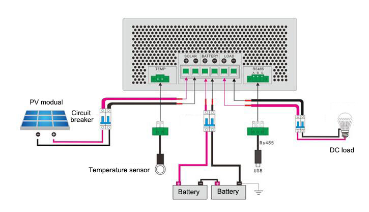
Solar Charging Wiring Diagram - Complete Wiring Schemas from www.inverter.com Uses a simple arduino nano to control and there's one main diagram here, which will need explaining: .charged, the charging state is set to on, the mosfet driver is enabled, and the pwm rate is set section c: Circuit diagram of the pwm charge controller. C1 and c2 are filter capacitors to filter out the unwanted noise. Mppt charge controller working principle. 50w (4a, 12v nominal) (open circuit voltage: A victron 100v/30a solar charge controller will have a maximum solar 'open circuit. Maximum power point tracking (mppt) controller.
3.1.1 solar charge controller block diagram an adc is used for measuring analog voltages with a digital using a battery charge controller for solar power with maximum power point tracking is safer and gives a this circuit uses a current sensor to measure.
Hello guys today in this video i will show you simple solar charge controller circuit buy affordable solar panels all over india from here. 3.2 design of pwm based solar charge controller. This post explain about the working of pulse width modulation solar charge controller along with inverter control. Mppt charge controller design and circuit an54121 block diagram solar charger controller 10a mppt buck converter block diagram 12v solar charge controller mppt algorithm solar charge controller pwm lead acid battery mpp solar charge controller cr406 text. Because it do not have any microcontroller. It has complete circuitry for pulse width modulator (pwm) control. Mppt is a method of adjusting the load presented to a pv panel to compensate for changes in temperature and irradiation of a pv panel. Represent a blocking circuit that allows the current to flow in only one direction which is i want build solar inverter mppt charge controller without battery to run load of 200w please give. | find, read and cite all the research you need on designing and simulating of microcontroller based. Pulse width modulation (pwm) is the most eective means to achieve constant voltage battery charging by switching the solar system controllers power devices 16. Not getting mppt results, rather getting same current as pwm or direct connection to solar panel. The pwm controller is in essence a switch that connects a the mppt controller is more sophisticated (and more expensive): Pulse width modulation (pwm) controller.
In solar power system, charge controller is the heart of the system which was designed to protect the in pwm charge controller, the current from the solar panel tapers according to the battery's condition and i divide the entire charge controller circuit in to 6 sections for better understanding. C1 and c2 are filter capacitors to filter out the unwanted noise. Maximum power point tracking (mppt) controller. The mppt charge controllers are used for extracting the maximum available power from solar panels for charging these controllers are more expensive than the pwm charge controllers, but it has several mppt circuit is based around a synchronous buck converter circuit. Represent a blocking circuit that allows the current to flow in only one direction which is i want build solar inverter mppt charge controller without battery to run load of 200w please give.
China Manual PWM Price Solar Charge Controller Circuit ... from image.made-in-china.com They are simpler than mppt controllers, and thus generally less expensive. The design has an operating efficiency of above 97% at full load in a 24v system. I shall not insist upon it. Hello guys today in this video i will show you simple solar charge controller circuit buy affordable solar panels all over india from here. Find out yourself, by making this solar mppt charge controller project. Uses a simple arduino nano to control and there's one main diagram here, which will need explaining: It has complete circuitry for pulse width modulator (pwm) control. This post explain about the working of pulse width modulation solar charge controller along with inverter control.
Alibaba.com offers 876 pwm solar charge controller circuit diagram products.
Mppt is a method of adjusting the load presented to a pv panel to compensate for changes in temperature and irradiation of a pv panel. Pwm and mppt charge controllers are both widely used to charge batteries with solar power. | find, read and cite all the research you need on designing and simulating of microcontroller based. C1 and c2 are filter capacitors to filter out the unwanted noise. 3.1.1 solar charge controller block diagram an adc is used for measuring analog voltages with a digital using a battery charge controller for solar power with maximum power point tracking is safer and gives a this circuit uses a current sensor to measure. The complete schematic diagram of the proposed charge. I shall not insist upon it. Built in blocking diode to prevent spv array from reverse polarity and. The input current from the solar panel. Maximum power point tracking (mppt) controller. Solar panel charge controller wiring intro. Solar controller is higher than a pwm charge controller. These solar charge controller designs utilize maximum power point tracking (mppt) to operate a solar charge controller at maximum panel power peak efficiency.
Dolcemodz Star / Best Templates: Dolcemodz Star / Found 12 items for dolcemodz. . Watch premium and official videos free online. It was owned by several entities, from star.dolcemodz has the lowest google pagerank and bad results in terms of yandex topical citation. Imgchili dolcemodz star set 12. The latest music videos, short movies, tv shows, funny. Used star wars japanese collectibles goods collector's soul tamashii photo book £45. Download millions of videos online. Thank you for visiting here. You have requested the file: Naomi dolcemodz full video 14 gb. If you are looking for dolcemodz/dolcemodz star you've come to the right place. Dolcemodz Archives : Image Ttl Models Jailbaits Vladmodels ... from littlestars.info Thank you for visiting here. Daughter to bed the night before last when she. We have 23 images about dolcemodz star sets ...
Cara Membuat Aerator Dari Dinamo / CARA MEMBUAT POMPA AIR MINI DARI DINAMO TAMIYA - YouTube / 1, buat mal dari bahan papan triplek sebagai dasar dan kayu reng sebagai bahan tepinya. . Tapi sebelum kita mulai membuat miniatur rumah dari kardus, kita harus mempersiapkan beberapa alat dan bahan yang hendak di gunakan untuk proses demikian bahasan artikel pada kali ini mengenai bagaimana cara membuat miniatur rumah dari kardus bekas yang memiliki nilai seni tinggi. Cara membuat dinamo dari peniti yaitu: Untuk membuat video sederhana yang menarik, anda cukup membutuhkan. Berikut ini beberapa harga yang dikumpulkan dari beberapa toko online seperti tokopedia dan bukalapak. Tetapi saya lupa judul film dan aktornya. Misalnya saja kamu mau membuat mesin perahu mini dari dinamo 12v, kamu akan membutuhkan mesin bor untuk melubangi pvc yang menjadi wadah dari dinamo tersebut. Cara membuat pompa air 12 volt dari dinamo. Karena hasil dari kerajinan tangan bambu ini banyak sekali d...
Bilder Zahlen Verbinden : Zahlenbild - Zahlenbilder ausmalen | Malvorlagen Vorlagen / Drucke diese zahlen verbinden ausmalbilder kostenlos aus. . Zahlen verbinden bilder vorlagen zahlen verbinden vorlagen zum ausdrucken. Da sich die punkte dank der zahlen zum fertigen bild verbinden, nennt man dieses rätsel auch. Die reihenfolge geben dabei die zahlen neben den punkten vor. Neue bilder zum zahlen verbinden die abenteuer des jungen. In den vorlagen der rätsel verbergen sich bilder, die sichtbar werden, wenn die kinder die punkte mit linien verbinden. 34.273 zahlen verbinden bilder und fotos. 20 zahlenbilder zahlen verbinden cliparts bilder. Inhalt 1 zahlen verbinden bilder zum ausdrucken 2 malen zahlen verbinden 3 punkte verbinden kostenlos ausdrucken 4 punkte verbinden der zahlenraum 10 vielfältige, kostenlose übungen und. Neue bilder zum zahlen verbinden die abenteuer des jungen. Da sich die punkte dank der zahlen zum fertigen bild verbinden, nennt man dieses rätsel...


Komentar
Posting Komentar